Structural Design I
The courses Structural Design I and II explain the fundamentals of how structures function. These courses put great emphasis on studying the relationship between the form of a structure and the internal forces within it by means of graphic statics.
Exercise 3: Cables
In the last exercise, simple cable structures were studied. The following exercise helps you to deepen your knowledge about form finding and more complex cable structures. You have to find thrust lines (cable forms) for cable structures with different loads.
Case Study: Panoramabridge Sigriswil
Investigation of a suspension bridge. Determination of forces and effects involved.
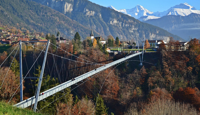
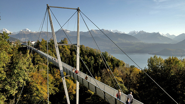
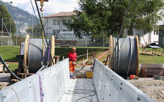
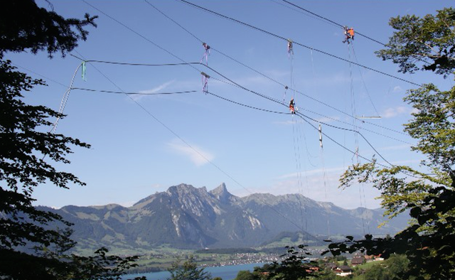
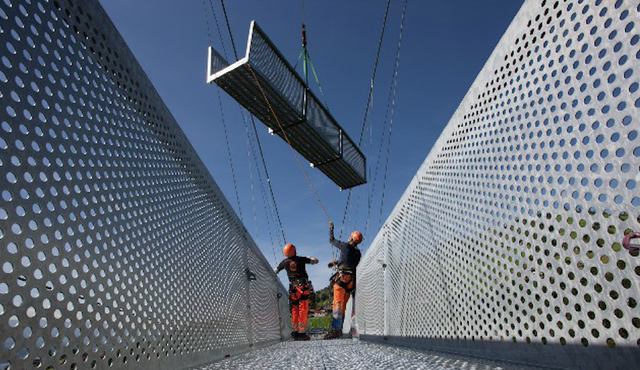
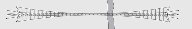
The panoramic bridge in Sigriswil was designed by the engineering firm Theiler Engineers AG, Thun, and built in 2012. With a height of 182 meters, it spans over the Guntenbach gully by the lake of Thun, making it an es-sential element of the project to build a panoramic trail around the lake. On one hand, the bridge is to provide a sense of safety and stability, and on the other it should provide an adventurous and challenging experience. This places the bridge between urban and alpine pedestrian bridges.
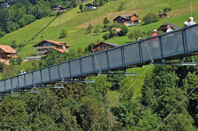
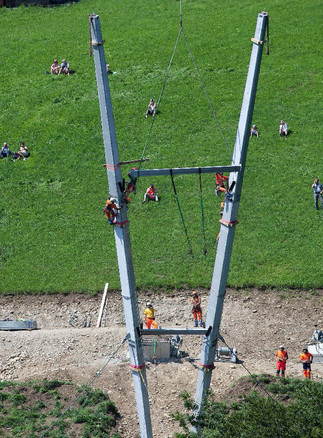
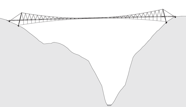
Its construction: the bridge is carried by four 27 meter high pylons that are slightly tilted. Three cables are se-cured at the top of each pylon – a main cable and two secondary cables to provide horizontal stiffness. The bridge passage is hanging from the cables by truss-shaped cables that are obliquely tensioned to improve the vertical and horizontal stability. A 3D model was used to exactly dimension the length of the cables, do the static and dynamic calculations and to visualize them.
- For the calculations, a uniform vertical dead area load of
gk= 1,0 kN/m2 and a constant variable area load ofqk= 0,7 kN/m2. These two loads act together along the entire length – 288 meters – and width – 1,5 meters – of the bridge deck between the pylons. Calculate the total linear load sd at the relevant level on the main cable including the safety factors and the resultant force of the point load R. - Next, we simplify the bridge into a structure composed by the main cable, pylon and the back anchorage. For case a), find the following values with the help of graphic statics and the assumption that the upper cable has a parabolic shape: the maximum load on the cable, the reaction forces, and the forces in the py-lons and the anchors. Note: take into account the symmetry of the bridge! Identify which elements are under tension and which under compression, and identify them on the location plan and the force diagram (red for tension and blue for compression elements).
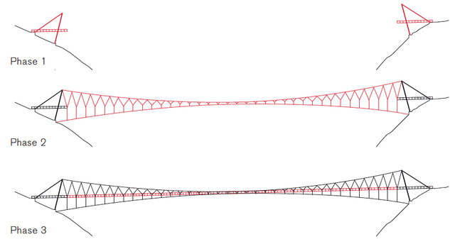
- Next, assume the construction section shown in figure d with a length of 8 meters. Find the point load Fd 1 based on the area load calculated in 1).
- Using graphic statics, divide the force d 1 into the forces on the main cable and on the bridge deck (For simplicity purposes, assume that force Fd 1 der acts directly on the node).
- Next, assume that the suspended cable carries a load equal to Fd 1 and that the force in the main cable remains unchanged. Find FSuspend and FDeck for this case.
- For the third case, the load in the main cable stays the same, but there is an additional point load Fd 2 acting on the node in the same direction as Fd 1 but with half the magnitude of Fd 1. Draw the force diagram and calculate FSuspend und FDeckfor this case.