Shaping trusses

Part A
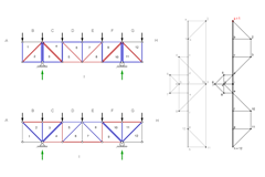
Compare the magnitude and type (compression or tension) of the internal forces in the horizontal, vertical and diagonal members of the two trusses in the drawing. The force diagram of the top truss is grey; the one of the bottom truss is black. Both structures are symmetrical and have the same loading. Note that the force diagram of the bottom truss can be moved over the force diagram of the top truss for comparison by dragging the red point.
What happened to the forces in the compared truss members?
Part B
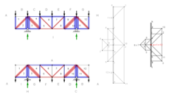
Compare the magnitude and type (compression or tension) of the internal forces in the horizontal, vertical and diagonal members of the two trusses in the drawing. The force diagram of the top truss is grey; the one of the bottom truss is black. Both structures are symmetrical and have the same loading. Note that the force diagram of the bottom truss can be moved over the force diagram of the top truss for comparison by dragging the red point.
What happened to the forces in the compared truss members?
Part C
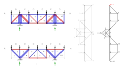
Investigate the effects of asymmetric live loads on the truss members. Through the application of three additional loads (live loads) at different nodes different load cases are created. Apply live loads by sliding the load handles up. Check all load cases in which three nodes are loaded with dead load and live load (slider of the load up) and four nodes with only the dead load (slider of the load down).
Which combination of live loads is the worst load case respectively the best load case for the truss member D6? Explain why the truss members 11-12, G-12, H-11 und H-12 are unaffected by live loads applied to the left of the right support.
Part D
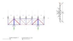
Geometry variation - find the lowest member forces Start from the original truss. Move only the upper joints vertically and find a geometrical configuration for the truss with the lowest possible member force.
Why have you solved the question in this way? Explain your approach.
Part E
Geometry variation – improve the result Use the modified truss. Move all joints vertically and find a better geometrical configuration for the truss as before.
Why have you solved the question in this way? Explain your approach.