Exam Summer 2012
Design of a suspended roof
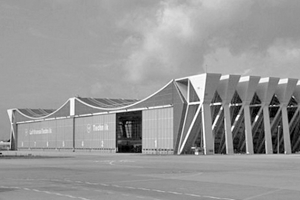
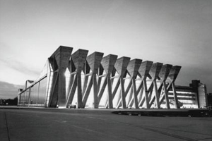
The Lufthansa Maintenance Hangar V is well-known for its size and capacity as well as its spectacular form. With its length of 320 meters, width of 100 meters and height of 23-43 meters, it can hold six Boeing 747 jumbo jets, or alternatively 14 Boeing 707 long-distance jets. In 1972, when the hangar was built, that was a world record. Its form results directly from the load-bearing structure, which consists of two suspended roofs. The thin pre-stressed concrete bands are supported by cables spanning between large truss-like support structures.
The task is to find the shape of a cable supported suspended roof taking into account its dead load and applicable live loads and to calculate the forces in the support structures. The shape of the roof is determined by the forces, which act on the structure. The roof consists of 10 lightweight concrete bands (width b = 7.5 m, material thickness t = 90 mm) with 30 steel cables (S500) embedded into each band, spanning across a distance of 130 m. Between the adjacent concrete bands there is a glazed opening. The loads to be considered for the roof are the concrete band (wgk = 1.85 kN/m2) and snow (wsk = 1.0 kN/m2).
Uniform loading
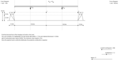
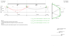
- In order to find the funicular shape of the suspended roof, calculate the line load as design load (uniformly distributed) for one of the roof bands and give its value in kN/m. The concrete bands (width b = 7.5 m, material thickness t = 90 mm) span between supports 1 - 2 and 2 - 3. There is a minimal height clearance of 22 m. Draw the form and force diagram for one suspended roof band (Steps 1-5).
- Indicate the maximum force in kN for this suspended roof band (Steps 6-7).
- Use the maximum force to dimension the 30 steel cables (S500) embedded into the concrete roof band. Give their diameter in mm (Step 8).
- Indicate the magnitude and the direction of the reaction forces at supports 1, 2 and 3 (Steps 9-12).
Click here to open the interactive drawing that shows the graphical solution. Use the slider in the bottom right corner to browse through the different steps.
Asymmetrical loading
- In addition to the dead load (concrete band), assume a live load (snow) between supports 1 and 2 only. Draw the form and force diagram for this loading case (Steps 1-5).
- Determine the magnitude and direction of the "new" reaction forces at supports 1, 2 and 3 required to achieve the same roof shape as in the first part of this exercise (Steps 6-9).
- What change in the geometry is required to achieve the same direction of the reaction force at support 2 as in the first part of this exercise? Indicate at least two possibilities (Steps 10-11).
Click here to open the interactive drawing that shows the graphical solution. Use the slider in the bottom right corner to browse through the different steps.
Calculation of truss-like support structures
Now we calculate the support structures of the suspended roof using a simplified two-dimensional version of the supports. The geometry of the two outer supports is identical; mirrored along the axis of symmetry of the roof. The middle support is reduced to only two steel members. The assumed load Pd which is acting on the supports is composed of the components PdV = 900 kN and PdH = 2500 kN.
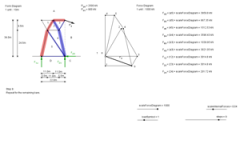
Outer support
- Confirm that the truss is statically determinate.
- Determine the reaction forces of the truss graphically (Steps 1-4).
- Determine all the member forces of the truss members and indicate their values (Steps 5-6).
- Indicate the character of the truss members using red for tension and blue for compression (Steps 7-9).
- The support structure is made of steel tubes ROR (S355) with a material thickness of t = 20 mm. Use the critical member in order to choose the diameter of the steel tube (Steps 10-11).
Click here to open the interactive drawing that shows the graphical solution. Use the slider in the bottom right corner to browse through the different steps.
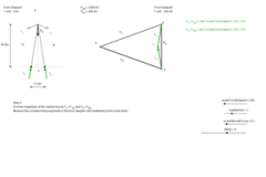
Middle support
- Determine the reaction and member forces of this truss graphically (Steps 1-6).
- Check if the steel tube determined for the outer support could be used for the middle support (Step 7).
Click here to open the interactive drawing that shows the graphical solution. Use the slider in the bottom right corner to browse through the different steps.