Exam Winter 2014
Design of a grandstand roof
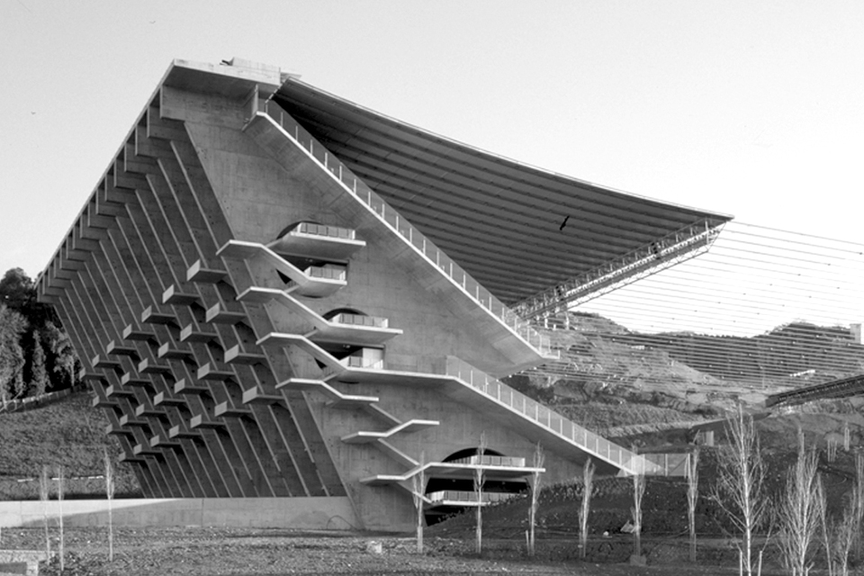
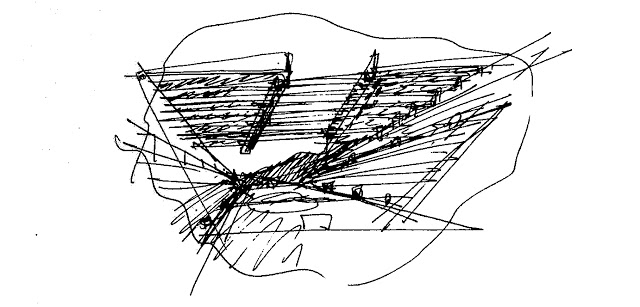
The football stadium in Braga, Portugal, was designed by Eduardo Souto de Moura for the 2004 European championship in Portugal. It can accommodate 30'000 spectators. The stadium was carved from a quarry that overlooks the city of Braga. Due to this specific location, the longitudinal sides of the football pitch are framed by two steep grandstands while the short sides remain open, facing the rock walls of the quarry at one end and the sprawling city at the other.
The steel cables of the hanging roof span between the two grandstands. The roof covering the grandstands consists of precast concrete panels which are supported by these cables.
The task is to calculate three different parts of the stadium roof.
The hanging roof - uniform loading
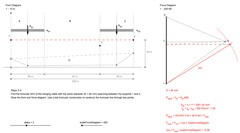
In the first part of the exercise, a simplified version of the hanging roof of the Braga football stadium is examined. The roof consists of a set of hanging steel cables (S500), spanning a distance of 205 metres between the two grandstands. The grandstands are covered by precast conrete panels which are supported by the hanging cables. Each concrete panel (width b = 3.7m, material thickness d = 240mm) is fixed to a hanging cable on either side. The only force to be taken into account is the self-weight of the precast concrete panels. Assume the material density of reinforced concrete with γ_{k} = 25 kN/m³.
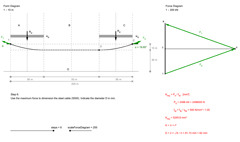
Find the form of the hanging roof for uniform loading.
- Calculate the line load wd (uniformly distributed) for one of the hanging cables and indicate its value in kN/m. Label the spaces and construct the loadline (Step 1).
- Find the funicular form of the hanging cable spanning between the supports 1 and 2 and passing through point 3. Draw the form and force diagram. Use the construction of a funiular line through three points to find the pole o (Steps 2-3).
- Indicate the maximum force for the hanging cable in kN (Step 4).
- Indicate the magnitude and direction of the reaction forces at the supports 1 and 2 in kN (Step 5).
- Use the maximum force to dimension the steel cable (S500). Indicate the diameter D in mm (Step 6).
Click here to open the interactive drawing that shows the graphical solution. Use the slider in the bottom left corner to browse through the different steps of the construction.
The hanging roof - aysmmetric loading
In the second part of the exercise, the hanging cables are examined under asymmetric loading. For the left side, the only force to be taken into account is the self-weight of the precast concrete panels with a material density of reinforced concrete γk = 25 kN/m³. For the right side, an additional snow load is to be taken into account.
Find the form of the hanging roof for asymmetric loading.
- Calculate the line load wd2 (uniformly distributed) for the right side for wd2 = wd1 × 5/3. Label the spaces and construct the load line (Step 1).
- Find the funicular form of the hanging cable with the same diameter (D = 82 mm) spanning between the supports 1 and 2. Draw the form and force diagram. Use a trial funicular construction to construct the funicular line through two points (Steps 2-3).
- Indicate the new cable sag h at point 3 in m. Indicate the maximum force for the hanging cable in kN (Step 4).
- Indicate the magnitude and direction of the reaction forces at the supports 1 and 2 in kN (Step 5).
Click here to open the interactive drawing that shows the graphical solution. Use the slider in the bottom left corner to browse through the different steps of the construction.
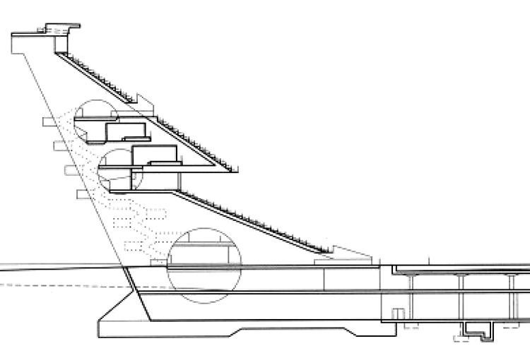
The grandstand
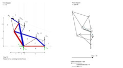
In the third part of the exercise, the concrete structure of the Western grandstand supporting the hanging roof is analyzed. In order to estimate the approximate stress in the reinforced concrete shear wall, a truss structure is superimposed onto the shear wall. The geometry of this truss has to follow the shape of the shear wall while taking into account its circular openings. The estimated load of the hanging cable supporting the roof is Pd2 = 2800 kN. The loads of the grandstand itself are assumed as four equal point loads Pd1 = 1500 kN. The self-weight of the structure does not have to be taken into account.
- Determine if the truss is statically determinate (Step 1).
- Label the spaces and construct the loadline (Step 2).
- Determine the reaction forces of the truss graphically. Find the resultant of the set of forces acting on the structure using a trial funicular polygon (Step 3).
- Draw a substitute system in which the reaction forces balance the resultant of the set of forces. Draw the force diagram and determine the magnitude of the reaction forces. Note that the letters used for labelling are irrelevant as long as their use is consistent in both form and force diagram (Step 4).
- Determine the magnitude of the reaction forces by measuring the corresponding segments in the force diagram and multiplying by the scalefactor (Step 5).
- Determine the magnitude of all the member forces of the truss members and indicate their values in kN (Steps 6-7).
- Indicate the character of the member forces using red for tension and blue for compression (Step 8-10).
Click here to open the interactive drawing that shows the graphical solution. Use the slider in the bottom left corner to browse through the different steps of the construction.